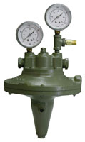
Oil Air Ratio Regulators
Selas Oil-Air Ratio Regulators (Product No. 5301) are used to proportion fuel flows to modulating oil burners.
Combustion air flows produce a proportional pressure signal that is applied to the regulator to set the outlet oil pressure. On initial adjustment the desired oil flow rate is set to match the burner air capacities. The regulator holds this oil to air ratio at all firing rates.
Pressure balancing of the oil control system eliminates complicated valve linkages on these burners.
Heat input turndown over a 10 to 1 range is achieved by varying the position of the combustion air control valve. This simple single valve control is readily interlocked with control motors to process temperature, pressure or other functions to provide precisely the heat required at any time.
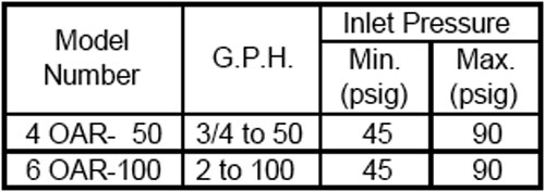
Oil-Air Ratio Regulators have a unique balanced valve design for inlet oil pressure in the 40 psig to 100 psig range. A constant oil pressure is required at the OAR inlet.
Capacity Table
Operation
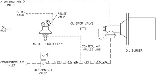
The OAR regulator will efficiently control #1, #2, and #4 grades of oil. A load line from the combustion air supply at least 10 pipe diameters downstream of the combustion air controlling valve is connected to the control air impulse line. A 1/4” load line is sufficient.
A reducing regulator should be installed upstream of the OAR regulator to provide constant oil pressure. A variation of 5 psig at the inlet can cause a 2% error in flow control.
Air pressure from the load line forces the main diaphragm upwards opening the oil outlet valve. The oil pressure in the outlet chamber applies pressure on the oil piston which opposes movement of the main diaphragm and tends to close the oil outlet valve. Since the main diaphragm has an area 30 times larger than the piston area, oil flows from the regulator at a rate that produces an outlet oil pressure 30 times the inlet air pressure. Since the air and oil orifices in the burner are a fixed size, a proportional change in oil pressure and air pressure results in a constant fuel-air ratio.
For 1 psig combustion air, a 45-50 psig inlet oil pressure is recommended. For 2 psig combustion air, a 75-80 psig inlet oil pressure is recommended.
The valve assembly, main diaphragm and springs move as a single unit. The main diaphragm area is 30 times larger than the seal or oil diaphragm area. The tension spring biases the compression or push spring to nearly atmospheric outlet pressure.
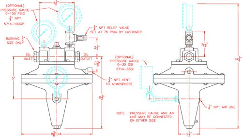
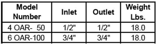
Dimensions: OAR Regulator
Typical OAR Control System
Installation Instructions
- The regulator should be installed in a horizontal line with the adjustment stem down. The arrow cast on the valve body indicates direction of flow.
- Inlet oil pressure to the regulator should be 10 psig higher than the maximum outlet pressure. (Example: 16 osi air pressure produces 32 psig outlet oil pressure. Inlet oil pressure should be 42 psig.)
- A fine mesh (0.003”) Oil Strainer or a (0.0035”) Edge Plate Filter must be installed upstream of the regulator to prevent clogging of the valves.
- The discharge of the Relief Valve should be piped back to the oil tank.
- *For optimum performance accuracy the regulator should be on the same level as the burners. Where groups of burners are on different levels, separate regulators should serve each level.
- Avoid long oil lines between the regulator and burners.
- If the low fire rate of the burner is less than two gallons per hour, install a constant bypass system.
Low Fire Adjustment
Initial Setting
NOTE: These instructions are for setting of the air-oil ratio and are not burner start-up instructions. Burner start-up can only be performed with knowledge of the complete system design.
Start with all safety valves closed. Check the air pressure to the burner and oil pressure to the OAR regulator. (For 16 osi air pressure, 42 psig minimum oil pressure is necessary.)
With the atomizing air on, the combustion air valve closed and pilot burner ignited, open the oil valve until the burner lights. Allow sufficient time for warm up of the refractory combustion block.
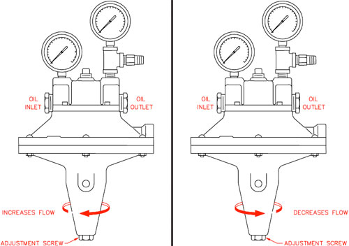
Slowly open the combustion air butterfly valve while simultaneously opening the oil valve to maintain a stable flame. Adjust the oil to air ratio for proper flame with the oil valve at high fire and lock. Return the burner to low fire and adjust low fire oil setting with the adjusting screw in the bottom of the OAR Regulator. (Turning the adjustment counterclockwise decreases the oil flow and clockwise increases the oil flow.)
After adjusting the low fire setting return the burner to high fire. Make any final ratio adjustments necessary with the oil valve. Once set, the burner system can be controlled by the combustion air butterfly valve only.
Ordering Information
- Specify Model Number and Quantity.
- Shipping Instructions.
Features and Benefits
- Precise control of outlet pressure.
- Pressure balance system for single valve control.
- 10:1 turndown ranges.
- 40 to 100 psig inlet oil pressures.
- 250°F Maximum Operating Temperature.
- Balanced valve design.
- Accurate 30:1 oil to air pressure ratio at all firing rates.
- Adjustable low fire setting.
- Designed for continuous service.
- Rugged, heavy-duty construction.