Ribbon Burner: Models, Design, and Operation
Your Combustion System – How Does It Work?
All fuels, whether natural gas, propane, butane, gasoline, or oil, require a certain amount of oxygen (O2) to burn. The oxygen can be supplied in its pure form to develop an extremely hot flame at a high cost or can be mixed with a noncombustible gas such as nitrogen (N2) at virtually no cost but at a lower heating potential. Since the air we breathe is composed of approximately 20% oxygen and 78% nitrogen, let us use air as our O2 source.
Requirements of Combustion
Next let’s consider how much air we need to burn a given amount of fuel. The chemical formula for natural gas (or methane) is CH4 (one carbon and four hydrogens). Without getting too technical, let’s assume that 1000 BTUs of any fuel requires 2 cubic feet of oxygen (or 10 cubic feet of air) for stoichiometric combustion, a fancy term for complete combustion of the mixture. When we mix 10 parts of air and 1 part of methane, we get the following formula:
CH4 + 2 O2 + 8 N2 ––––> CO2 + 2 H2O + 8 N2 + heat
Methane plus oxygen yields carbon dioxide plus water plus heat
(Note that the nitrogen travels through the combustion without a change)
This example assumes the air and gas to be pure and everything to be easy. In reality, the air has 2% other gases (not enough to worry about) and the methane gas contains all manner of other stuff. In fact, the exact composition of a gas supply is rarely consistent. Most of the time, in addition to methane, there will be traces of butane, ethane, propane, carbon dioxide and nitrogen present in any given sample. Even so, unless we need to deal with a laboratory situation, a simple ratio of 10 cubic feet of air to 1000 BTUs of gas will almost always suffice. This rule holds true whether the gas is methane (which has about 1000 BTUs per cubic foot), propane (2500 BTUs per cubic foot), or butane (3200 BTUs per cubic foot). This means that to burn completely, 1 cubic foot of methane requires 10 cubic feet of air; 1 cubic foot of propane requires 25 cubic feet of air; and 1 cubic foot of butane requires 32 cubic feet of air.
Mixing Air and Gas
Now we must consider how to mix the air and gas.
- We could just blow raw gas through a hole and let it mix and burn in the open. This is the simplest of burners and is known as an atmospheric burner. It produces a flame which is long and lazy. This is due to the inability of the air to mix with the gas fast enough via natural convection.
- A better solution would be to employ an inspirator to utilize the pressure at which the gas is delivered to induce air into the mixture. The BTU capacity of an inspirator can be precisely figured because, given the gas pressure, the orifice size, entry conditions, and type of gas, there is an Orifice Flow Formula that will calculate how many cubic feet of gas will pass through. This information is summarized in gas orifice tables for each size of orifice at various pressures. Ribbon Burner Tutorial 2 3 2. (continued) Having the gas volume gives us the BTU capacity but doesn’t tell us how much air will be mixed with this gas. By convention, the energy of the gas stream can induce approximately 40% to 60% of the air needed, so for 1 cubic foot of methane we can get 4 to 6 cubic feet of air. The balance of air is provided from the atmosphere at the point of combustion. If we consider the pressure of the gas coming out of the orifice, and its volume, and add the air at atmospheric pressure, we can see that the mixture pressure developed is approximately 1/7th to 1/5th of the supply pressure (generalizing the result by ignoring the fine details). Of course, this result also depends upon the selection of inspirator which must follow the same rules as the orifice flow equations. A smoothly rounded entry point with gradually opened throat will produce the highest efficiency flow and allow for the greatest air entrainment percentage. While an inspirator provides a better mixer than raw gas out of a hole, it is still somewhat inefficient. Due to its low cost, however, the inspirator is often the mixer of choice in terms of both initial cost and operating expense.
- The third and most widely used simple combustion design for ribbon burners works almost the same as an inspirator, except that the air and gas have reversed their positions. Now the air is pressurized to provide the motive force to draw in the gas and, like the inspirator flow, can draw approximately 4 cubic feet of gas to 1 cubic foot of air. This proportion gives an extremely rich mixture. The gas must therefore be restricted to limit it to the correct gas-air ratio. The gas is connected through a specialized pressure regulator called a Zero Gas Governor, which reduces the gas pressure to whatever the atmospheric pressure is at that time. Proper combustion requires 1 cubic foot of methane per 10 cubic feet of air, a 1:10 ratio. Since this mixer system can draw so much more gas than is needed, it is easily adjusted to either rich or lean as the process demands. Adjustment of the gas orifice will provide this control. Once the air volume is fixed and the gas is adjusted for that air flow, the physics of mass flow take over. This means that adjustment of the air volume will directly correspond to the amount of gas dragged in. If we start with 10 cubic feet of air and 1 cubic foot of gas and we turn down to 1 cubic foot of air, the gas will automatically decrease to 0.1 cubic foot. Now we can control the firing rate using simple air volume flow controls like a butterfly valve or needle valve. This system is generally the one in use in bakery operations due to its simplicity, reliability, and flexibility of heating patterns (each burner can be individually adjusted for the heat input needed at that point of the cycle).
- The final common type of combustion supply is a premix or mechanical system. This usually entails a blower with a gas feed, in which the room air is drawn in and the gas is forced into the incoming air stream in such a way that the mechanical action of the rotating blower wheel thoroughly mixes the air and gas. This style mixer is generally used with large port area burners but can be used with almost any burner provided the feed pipe is large enough. In other words, if the blower has a 2-inch diameter outlet, you will want to connect it to a 2-inch or larger burner feed. If the burner is smaller, then the air/gas mixture will back up in the blower and may create problems.
Flame Safety and Exhaust Requirements
The essence of flame safety systems is the requirement that the fuel mixture will be ignited without resulting in any part of the system reaching the LEL (Lower Explosive Level). This is the point below which the gas/air mixture will not support combustion (mixture is too lean). This is accomplished first by purging any enclosed combustion chambers for the period of time it takes to change the air 4 times. Next, we use a flame safety that starts ignition prior to allowing gas entry. Under NFPA (National Fire Protection Association) rules, we have 10 seconds to attempt to light and prove a burner, after which the system must be shut down. In addition, if the flame signal is lost for any reason, the ignition must come back on instantly and if ignition is not proven in 4 seconds, again the gas is shut off.
Gas Supply Valve Requirements
The NFPA requirements state that all burners must be designed with two automatic safety valves. These are usually wired in series with the air pressure switch, low gas pressure switch, high gas pressure switch, high temperature limiting switch, and purge completion switch. This valve would then shut down the entire system in case of any failures. Systems utilizing less than 150,000 BTUs require no additions to the valves. Between 150,000 and 400,000 BTUs, both safety shutoff valves must have visual indication of valve position. Additionally, above 400,000 BTUs, one valve must also have a proof of closure switch interlocked to the safety system. Factory Mutual (FM) and Industrial Risk Insurers (IRI) require their own additions, either a switch to prove valve closure or vent valves between the main gas valves.
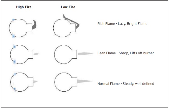
Flame Characteristics
Pipe Manifolding Calculator
Pipe sizes in first column will allow for number of outlets shown in table when sized accordingly.
| Size | 1/8 | 1/4 | 3/8 | 1/2 | 3/4 | 1 | 1-1/4 | 1-1/2 | 2 | 2-1/2 | 3 | 4 | 5 | 6 | 8 |
| 1/8 | 1 | ||||||||||||||
| 1/4 | 2.1 | 1 | |||||||||||||
| 3/8 | 4.5 | 2.1 | 1 | ||||||||||||
| 1/2 | 8 | 3.8 | 1.8 | 1 | |||||||||||
| 3/4 | 16 | 8 | 3.6 | 2 | 1 | ||||||||||
| 1 | 30 | 14 | 6.6 | 3.7 | 1.8 | 1 | |||||||||
| 1-1/4 | 60 | 28 | 13 | 7 | 3.6 | 2 | 1 | ||||||||
| 1-1/2 | 88 | 41 | 19 | 11 | 5.3 | 2.9 | 1.5 | 1 | |||||||
| 2 | 164 | 77 | 36 | 20 | 10 | 5.5 | 2.7 | 1.9 | 1 | ||||||
| 2-1/2 | 255 | 120 | 56 | 31 | 16 | 8 | 4.3 | 2.9 | 1.6 | 1 | |||||
| 3 | 439 | 206 | 97 | 54 | 27 | 15 | 7 | 5 | 2.7 | 1.7 | 1 | ||||
| 4 | 867 | 407 | 191 | 107 | 53 | 21 | 15 | 10 | 5.3 | 3.4 | 1.4 | 1 | |||
| 5 | 1525 | 716 | 335 | 188 | 70 | 29 | 19 | 17 | 9 | 6 | 2.4 | 1.8 | 1 | ||
| 6 | 2414 | 1133 | 531 | 297 | 93 | 51 | 40 | 28 | 15 | 9 | 3.8 | 2.8 | 1.6 | 1 | |
| 8 | 4795 | 2551 | 1054 | 590 | 147 | 80 | 58 | 55 | 29 | 19 | 7.6 | 5.5 | 3.1 | 2 | 1 |
Burner Adjustments
Total Flame Capacity
On each air/gas mixer is an air control valve, which can be rotated to provide control of the flame. Fully opened, clockwise rotation provides full air to the burner. Likewise, counter-clockwise rotation will provide minimal air, and therefore a lower flame size.
Air/Gas Mixture
Above the air butterfly valve and to the side of the mixer body, there is a gas cock. A cap covers the gas proportioning screw. By removing the cap, and then by turning the screw in (CW) or out (CCW) the ratio of gas to air can be adjusted. The proper setting is achieved when the flame sits on the burner surface, without gaps and “blow offs.” When proper mixture is obtained, the cap should be replaced. Due to the use of a zero gas regulator, the burner mixture ratio will now stay the same regardless of the setting of the air valve.
Spark ‘N SenseTM Ignition
The Spark ‘N SenseTM module contains an output connection for both high voltage and flame sensing. Make sure this wire does not run with any other electrical cables to avoid noise. The ignition electrode must have a 1/8” gap to spark across, and is usually at the feed end of the burner. The sensor electrode will need at least 1/2” of electrode tip fully immersed in the flame, without being close enough to short circuit to ground.
Troubleshooting
If the burner fails to light, there is usually either too much or too little gas available. First check that there is air coming out of the burner. If the air comes through the mixer, then you need to check if the gas is being induced or not. Too much gas usually will result in a flame, but the flame will be very long and weak, the spark monitoring will not be able to sense it and the unit will shut off again. If the gas is too lean, the burner will just refuse to light at all. It is very important to check the gas proportioning screw (under the cover) of the gas cocks. Normally, you start with the screw backed out from the fully closed position about 4 or 5 turns and adjust from there. If a burner lights and then fails at approximately 10 seconds, this is an indication that the sensor failed to read the flame. If failure occurs later (after a few minutes), the problem may be traced to two possibilities. First, the electrode tip has moved when it heated up (it is normal for it to glow red), causing it to contact ground, and thus shutting off the burner. By the time you get back to it, it may look as if nothing is wrong, so after noticing a few failures, watch that burner continuously until it goes into failure. Second, the burner may fail due to the oven having reached temperature, and thus the burners move to low fire. At this point, the flame may no longer contact the flame rod. Generally, the minimum firing rate needs to be turned up, as the extremely low mixture pressures which work with continuous ignition are now too low. If this higher minimal flow causes the temperature to override the set point, then you need to use fewer burners.
| Download the full PDF for more information and data, including:
|
 |
MOST POPULAR RIBBON BURNERS:
ERB QuadCool Ribbon Burner
ERB’s SheetFlame ribbon design is port free and provides a uniform flame pattern producing striation-free product surfaces.
High Capacity Sheet Flame Burners
Designed for lamination and in the treatment of plastic film, foil, textiles, non-woven fibers. Constructed so all irregularities and breaks in the flame are eliminated.
ERB Special High-Capacity Triple-Slot Burners
At 60,000 BTUs per inch, these direct impingement linear burners are the most powerful in the industry.
Stainless Steel Ribbon T Burners
Designed for limited space applications requiring concentrated heat patterns, they provide a wide range of flexibility with respect to capacities, flame patterns and sizes.
RIBBON-STYLE PIPE BURNERS:
ERB Hi-Tri™ Trizone Burner
Features a new 2″ 2-tube arrangement to improve heat recovery time and reduce waste in baking and other critical applications. Replaces the older 1.5″ black pipe models for higher turndown.
ERB Black Pipe Burner Schedule 160
Twice as heavy as our standard Schedule 80 pipe burners.
RIBBON-STYLE LINE BURNERS:
Pyronics® Pyroline™ & Midget Pyroline Burners
Pyroline Burners are cast iron, drilled port continuous line burners with alloy side rails. Midget Pyroline Burners are low capacity, blast, line type units.
Download the full PDF for more information and data, including:
- Burner Adjustments
- Pressure Conversion Table
- Standard Pipe & Thread Table
- Propane Standby Systems